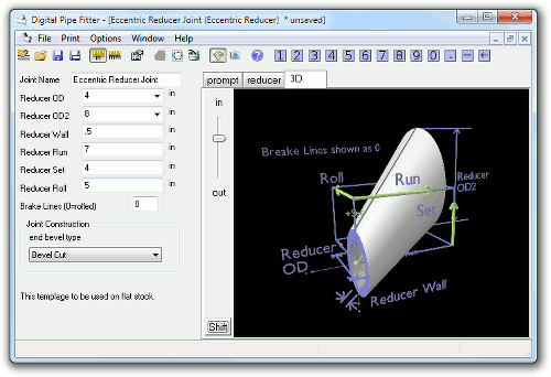
The Eccentric Reducer is not a joint. It is a template for forming a reducer out of a sheet of material. Each end of the reducer has circular openings which are parallel to each other. Each end diameter is independently controlled. The position of the second end can be controlled relative to the first with the same Run, Set, Roll settings found in a Rolling Offset Joint. Additionally, the user can optionally specify the number of brakes (or bends) in the end product. The number of brakes is always an even number (the same number of bends on each side of the axis) so the value entered is rounded up to the next even number. If the eccentric reducer is going to be rolled into shape, then specify a value of zero for the Brake Lines field. Remember that if eccentric, the final shape of the resulting reducer is not a cone but is often oblong in shape. Bend the component into shape so that the end openings are round.
The template generated is intended to lay on flat material before is is formed into a reducer. Marks are shown on the template to indicate location of each bend. Because this is a bent component, the ends of the reducer will not usually be flat surfaces ready to set up against the end of a pipe, Some hand preparation will be necessary.
Parameter Constraints:
Joint Name: name of this joint which is unique to this project or currently opened joints
Reducer OD: the Outside Diameter of the fixed end of the reducer. Must be a positive number
Reducer OD2: the Outside Diameter of the second end of the reducer. Must be a positive number
Reducer Wall: must be a positive number, less than half of the smallest end diameter
Reducer Run: a positive number representing the perpendicular distance between the two parallel ends
Reducer Set: the vertical distance the second end of the reducer is moved up and down from the axis of the fixed end.
Reducer Roll:the horizontal distance the second end of the reducer is moved to the side from the axis of the fixed end.
Number of Brakes: the total number of brakes (or bends) to be made, including the joint where the two sides of the material meet. This number is rounded up to the nearest even number so there is always the same number of bends on each half. Set this value to zero (0) if the component is to be rolled. A rolled component is approximated by a very large number of brake points.
Joint Construction: end bevel type:
Mid Point: The edge of the plate is cut perpendicular to the surface so that after being rolled or bend with a brake into shape, the midpoint (between OD and ID) of the bevels on both ends will be positioned at the midpoint of a pipe of the specified diameters.
Bevel Cut: The edge of the plate is cut at an angle so that after being rolled or bent with a brake into shape, the edges on both ends will be flat against the surface of the adjoining pipes.
Hand Bevel: The edge of the plate is cut perpendicular to the surface so that after being rolled or bend with a brake into shape, the ends can manually be ground flat to result in a flat surface (like the Bevel Cut above).

