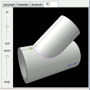
 The 3D render preview tab unveils what makes Digital Pipe Fitter so easy to use. You get to see exactly what your physical joint will look like when complete.
Holding the left mouse button and dragging it around the screen will spin the 3D rendered joint so you can view it from all sides. Holding the shift key on the keyboard while holding the left mouse button will pan the image around the screen.
The in/out slider zooms in and out. Holding the right mouse button and moving the mouse forward and backward will also control the zoom of the 3D preview.
If more than one component is shown on the 3D preview, the asm/exp slider assembles and explodes the assembly so that you can see how the components of the physical joint go together and view the inside structure of the joint. Holding the shift key on the keyboard while holding the right mouse button will allow control of the distance between components with mouse movement.
It is possible to view the cutlines and template axis wrapped around the 3D render. This makes understanding of the orientation of the components in the 3D render window much easier. To enable this feature, click the 'Annotate 3D' button in the button bar or check the 'Annotate 3D' checkbox in the settings window (menu: Options/Settings).
The annotations are very similar to those on the template as describe in the printing templates section of this manual. But there are several additional items drawn to help the user.
- Components are labeled with their componet name.
- A dot is drawn on the central axis of the component at the location where the vertical axis of the template is labeled zero. For a branch joint, for example, this marks the point where the branch intersects the axis of the header. This dot has a small tail leaving it pointing in the direction of positive values of the length axis of the component. If this tail were to be drawn on the 2D template, it would begin at point 0,0 and point downward.
- The rotational orientation of the component is indicated in the 3D view as a dark line on both the interior and exterior of the component. This line indicates the 'top' side of the component. It is analogous to the vertical axis on the 2D template when drawn at 0deg rotation.
- Cutlines are drawn with the same color and style as the template. They can be controlled or individually disabled on the settings window (menu: Options/Settings). These 3D cutlines are drawn at a distance above the surface of the component that is one half the value set by 'template thickness' in the settings window. This is because of the deformation of a thick template. The 3D line drawn is the actual lenght of the line printed to a template. It is not the length of the line on the top of the template that has been stretched to wrap around the pipe.
- Cone components have lines around the ends of their specified shape to show their position in space.
- Joints that include a setting for Split At will show a dashed line at the point around the pipe or cone where the template ends meet. This feature is most often available on joints that generate flat templates to be rolled after the template is transfered to the material.
- Some of the more complex joints include an axis showing a reference for the angles from 0 to 360deg and offset direction - or +.
Ordinate lines are not shown in the 3D render even if they are enabled for the template.
While viewing a 3D preview, pressing the Shift-F6 keyboard combination or pressing the camera icon on the button bar will save an image of the 3D preview to a file. If you want to print the resulting image, you might want to change the 3D Render background color to white on the Options/Settings screen. Holding down the Ctrl button when performing this function will result in a 3d model .wrl file of the 3D preview contents being saved.
