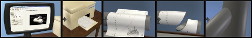
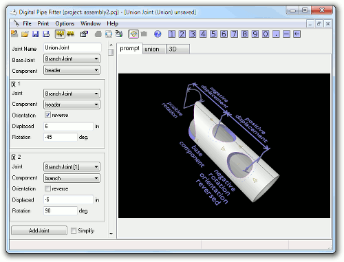
The Union Joint is a utility joint that allows cuts from a common sized component of multiple joints to be combined into a single template.
Parameter Constraints:
Name: name of this joint which is unique to this project or currently opened joints
Base Joint: the Joint Name of another currently open joint that contains a component (a tab label) to add cuts to.
Component: The component of the base joint that will be used as the base component of this union joint. This will be one of the tab labels from the Base Joint window. All other components to be combined with this one must have compatible shape and size.
The following parameters are repeated for as many joints have been added to the union. (See 'Add Joint' button description below.
Joint: the joint name of the currently open joint which contains a component to be added to this union template.
Component: The component of this joint you wish to add cuts to. This will be one of the tab labels from the Joint window. The component must be the same shape and size (both interior and exterior dimensions) as the base joint component selected above.
Displacement: the distance that this component's cut is to be slid along the Base Joint. The direction of the slide is indicated by the axis on the preview window of the base component. Usually, positive values will be in the down direction on the template preview. With a displacement of zero, pipes and plates will align with joint intersect points (vertical axis of zero), cones will align with the end of the cone component.
Orientation: if checked, this component is rotated (flipped end for end) before adding it to the union template. This is useful, for example, when adding a branch joint that can only have a branch angle between 0 and 90 degrees. If you want the added branch to extend to what would be greater than 90 degrees, then check this option. Starting in version 1.80, a cones orientation will be automatically selected based on the shape of the component so that the end diameters match that of the base component.
Rotation or Shift: A component's cuts can be shifted left or right on the template. For pipe or cone shaped base components, this is a rotation relative to the base component. Positive values are clockwise when viewed from the positive or bottom of the template end of the base component. For a plate shaped base component, positive values specify the distance to move this component's cut to the right. Negative values move this cut to the left.
The following functions are also available:
Add Joint: click this to add another component to the union. Remove a component by clicking the X in the upper left corner of the component parameter box.
Simplify: Some times if several end joints are combined onto one union template the results can be confusing and the user might not know what line to cut on. Checking the simplify checkbox will reduce the end cuts down to a single cut. Through hole cuts remain individually drawn for alignment purposes, even if through holes overlap, it usually is easy to tell where to cut.
Joint Construction:
Joint Constructions of the individual cuts are dictated by the constructions selected on the currently open joint windows referenced by the union joint.
Other comments:
Be sure to use 'Save Project' to save your union joint so that all currently opened joints are saved into one file for future use. If you just use 'Save Joint', then only the union joint is saved and not the referenced component joints.