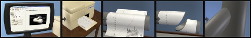
The lines on the template and Print Preview are rendered with the colors specified in the settings window. You may download this sample printout of a template to follow along.
Exterior Cut Line:
The exterior cut line is always drawn. It shows where to cut. If it appears without an interior cut line, then the intent is to cut along this line with the cutting tool perpendicular to the surface of the pipe.
Interior Cut Line:
The interior cut line is only printed for bevel cut construction types. This line indicates where to cut on the interior of the pipe. You will need to visually project the line toward the centerline of the pipe and estimate where it intersects the interior surface of the pipe.
Axis:
The axis is marked in the current units of the joint being printed. The angle measure on the horizontal axis can help in registration of the template on the pipe.
The axial measurement assumes that 0 is the point of intersection of the centerlines of the two components (or pipes). If the shapes of the two components are not pipes, this definition may change. For example if intersecting a flat plate, the 0 point is where the center of the pipe intersects the top surface of the plate.
After you print a template, check the axis measurements with a ruler to make sure your printer is printing to the proper scale.
On a cone shaped component, the vertical axis measurements show the distance along the axis of the component. It is not a measurement along the outside surface of the cone. The measurements do not represent linear distance along the template. This scale will be expanded depending on the flare of the cone.
Guide Lines:
Additional guidelines are show to aid in the alignment and interpretation of the template.
180deg and 90deg alignment lines:
Dashed alignment lines are shown where the template should meet on the far side of the pipe. If these two lines do not coincide when wrapped around the pipe, either the pipe diameter specified was not correct or the template thickness setting on the Settings window needs to be adjusted. Or perhaps your printer is not printing accurately. 90deg and 180deg dashed alignment lines are also shown to help align the template. Also, a scale on the horizontal axis shows angles of rotation around the pipe so the template can be oriented at any angle of rotation from an existing feature on the pipe.
Alignment Triangles:
Triangles are shown on each cut line to help align multiple components. These triangles (or diamonds) are pointed toward the waste side of the cut. Think of it in terms of, "cut along this line so that the triangle points toward the waste side of the cut. The triangle is located at the same point on both templates to aid alignment after cutting. You might want to make a mark on the exterior of the pipe at that point before removing the template to aid in assembling the physical joint. The triangles contain a character to indicate the type of cutline they are associated with.
- 1 - A first end cut: the waste side is above cutline as shown on the screen.
- 2 - A second end cut: the waste side is below cutline as shown on the screen.
- H - A hole cut: this cutline shows a hole cut in the side of the component.
- P - A plug cut: the opposite of a hole cut, cut on the outside of this cutline and use the material inside the cutline as part of the joint.
Keep Side Hash Marks:
On complex joints with many cutlines, it would not always be obvious which side of the cutline to cut on. So, hash marks are drawn on the side not to cut on. The marked side is the side of the cutline to keep. The waste side will not have hash marks. These marks are not generated for .DXF output files.
Ordinate Lines:
If enabled in the "Options - Settings" window, ordinate lines have several purposes. First, when shown in a printed report they specify the location and number of points shown for hand layout. Also, they help orient the user to know which side of the cutline is the waste side. The base band is always on the pipe side of an end cut.
Page markings:
Blue page markings are also provided on the Print Preview to help you decide what pages to print out and to know how many pages will be printed. These marks are not printed on the actual printout. Alignment marks are added to the printout to aid in aligning multiple pages together. Each printed page also has a small picture of where this sheet fits into the whole collection of pages.
Parameter Settings:
The parameters for a particular joint are printed on the first page including the joint name and the type of joint. If you are cutting out the template and saving it for future use, these parameters may be cut off. It is recommended in this case that you also print out a report (Menu: Print - Report) which you can keep with the template sheets so you know what settings were used to create that template.